
Technical principles
As well as conventional transformers, also Rogowski coils can be used for measuring current. The absence of an iron core means that no non-linear effects arise. Rogowski coils are easy to attach and remove without disconnecting the power circuit, i.e. without significant assembly work.
In contrast to transformers, high short-circuit currents in energy distribution do not cause high forces or losses when Rogowski coils are used. In addition, no residual magnetic or saturation effects detrimental to measurement can arise, unlike those occurring in normal transformers and requiring laborious demagnetisation.
Equally, no dangerous voltages can be generated in open operation, and so this causes no risk to electricians.

Figure 1: Rogowski coil with primary conductor
As can be seen in the figure, the output signal of the passive Rogowski coil is a voltage signal which is proportional to the change in the primary current. If the primary current is a 50 Hz sinusoidal signal, as is usual for electrical energy distribution in Europe, then the following expression results.

In order now to determine the slope of the tangents at point t, function i1 with respect to t is derived. The following equation results:

Accordingly, the output voltage of the Rogowski coil is proportional to the derivation of i1 with respect to time. Because the cosine function is displaced by -90 ° with respect to the sine function, the voltage signal ui is similarly displaced by -90 ° with respect to the primary current i1.


Figure 2: Primary current and output signal of a passive Rogowski coil in comparison
If the Rogowski coil is now matched (at 50 Hz) to the current signal to be measured, then by taking into account the transmission factor and the phase shift of -90°, it is possible to calculate back to the current i1. If the signal’s rated frequency now changes, then the amplitude value is affected by u1 as well.

These effects can be nullified in an electronic integrator circuit. Here, from a mathematical point of view, the derivation is integrated with respect to t. The cosine function becomes the sine function again, and the phase shift of 90 degrees is nullified. Using an integrator which provides a current signal as an output, the following equivalent circuit results.
Figure 3: Electrical Äquivalent circut for Rogowski Coil + 1A integrator
The Rogowski FASK coil
The MBS Rogowski model FASKs are supplied in four different diameters
(100, 150, 200 and 300 mm). An insertion point is provided on the closure; this is for a cable tie to attach the coil to the primary conductor.

Figure 4: The Rogowski coil FASK 150
General attributes
In order to achieve the maximum accuracy possible when measuring using Rogowski coils, the following items must be noted:
- In order to avoid parasitic effects, the Rogowski coil, including the supply cable, must be completely shielded.
- The output voltage of Rogowski coils is usually specified in mV/kA. Because voltage signals are generally deemed to be relatively failure-prone, the coil on the output should generate as large a voltage signal as possible because when smaller primary currents flow the output signal can be affected by noise or interference signals, and so the stated accuracy classes can no longer be achieved.
- The position of the primary conductor often affects the accuracy. When installing, it should be ensured that the coil is fitted so as to achieve the best accuracy.
Benefits of the Rogowski FASK coil
- The Rogowski FASK 100, 150, 200 and 300 coils are completely shielded, and are therefore extensively protected from interference effects
- All Rogowski coils generate a relatively large output signal of 100 mV/kA. Because of the coil’s good linearity, even relatively small primary currents well below 1 kA can be measured accurately.
- The Rogowski FASK coils have a phase error between -0.4 and -0.5 degrees, and so a fixed correction factor can be used in the measurement device.
- The materials permit use in very aggressive ambient temperatures. The coils generate no waste heat.
- The supply cable can be shortened without loss of accuracy.
As with any Rogowski coil, the positioning of the primary conductor affects the accuracy. The FASK series is designed so that the smallest error arises directly at the closure, i.e. in the attachment area. The following figure clarifies this situation and defines the exact error values.
FASK 100,150, 200 und 300

Figure 5: Position of Primar conductor, with typical error values

Installation
These sensors are extremely easy to install. Just a few simple steps are required to position the coil around the primary conductor and to connect it to the closure. The primary conductor does not need to be disconnected.
FASK 100,150,200 und 300
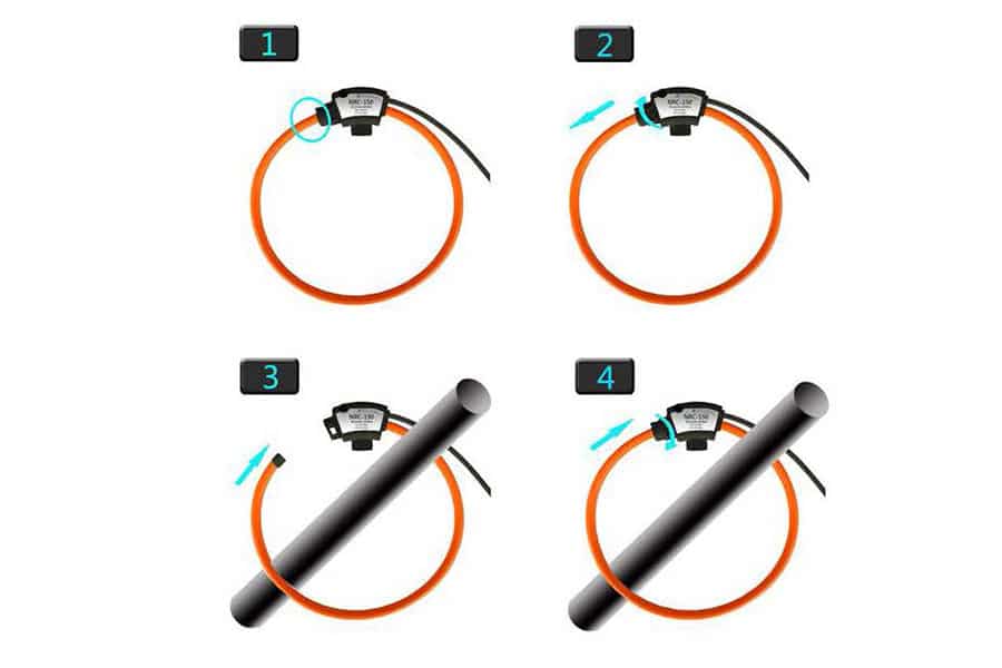
Figure 6: Installation of the FASK
Technical Parameters

Materials used

Safety

Dimensions
FASK 100,150,200 und 300


Figure 7: Further dimensions of the FASK 100, 150, 200 and 300
The ROI-3 integrator
In order to correct the phasing of the passive Rogowski coil by 90°, an integrator circuit is necessary. At the same time it is desirable to maintain a standard signal, in order to ensure compatibility with the usual measurement devices. The three-phase ROI-3 integrator is ideally suited to an output of 1 A. Three Rogowski coils can be connected simultaneously. A 24V DC source is required as the voltage supply. Installation on a 35 mm-DIN top-hat rail is intended.

Figure 8: Three Phase ROI-3 integrator
How the ROI-3 works
- An integrator is essential in order to balance the output signal of the Rogowski coils and to shift it by 90 °. The integrator consists of an active electronic circuit with negligible offset and good linearity.
- The output voltage signal of the Rogowski coil is converted to the 1 A standard signal.
- The output voltage signal of the passive Rogowski coil is proportional to the frequency of the measured current. The installed equaliser guarantees a signal which is linear to the primary current over a wide frequency range.
- When ordering in connection with the Rogowski FASK coil, the primary rated current must be specified. A fixed transmission ratio results, as for a standard transformer (e.g. 1,000/1 A). The primary measurement range
0 to 1000 A is mapped to the secondary measurement range of 0 to 1 A.
Benefits of the ROI-3
- Compact casing for the connection of three FASKs
- The ROI-3 does not measure direct currents when used with the FASK; however, in contrast to a transformer it can perform exact measurements of the alternating current component, even if a large superimposed direct current component is present, because there is no iron core to cause saturation. This function is particularly important for the measurement of ripple currents, e.g. in battery charging systems
- The ROI-3 integrator has relatively good frequency behaviour.


Figure 9: Frequency transmission behaviour of the ROI-3 with a FASK 150 (amplitude error and phase error)
Dimensions

Figure 10: Dimensions and connection diagram ROI-3
Specification
